Bow Tie Basics Part 2 Building Blocks-Basic Engine Configurations
Text by Bob Melilbeff Photos by Ed Tayler and Chevrolet
ボータイベーシック その2
ブロックを作るー基本的なエンジン定義
文章 ボブ メリルビフ 写真 エド テイラー と シボレー
| A hot-looking induction system, a set of good-flowing cylinder heads, and a strong cam. All these components have something in common. They're all bolted to an engine block that at one time began as a drawing. Since many of the performance characteristics of any engine depend on its block configuration, engineers must take into account an almost endless list of design criteria. The number of cylinders, bore size, stroke, vehicle design, and casting material must all be considered before designing an engine. Let's take a look at the cylinder block for this month's Bow-Tie Basics. » | 速そうな吸気システム、流れのいいシリンダーヘッドと強いカムの組み合わせ。これらの組み合わせは共感のあるところである。これらは全て最初は図面であったエンジンブロックに装着されている。あらゆるエンジンの多くの性能の違いはそのブロックの定義に影響を受けるため、エンジニアはほとんど無限にある設計要素のリストを考慮に入れなければならない。シリンダーの数、ボアのサイズ、ストローク、車のデザイン、鋳込む材料などは全てエンジンを設計する前に熟考されなければならない。今月のボータイベーシックとしてシリンダーブロックについて見てみよう。 |
 1
The Cylinder Block 1
The Cylinder Block
The block forms the basic framework of the engine where heat energy is converted into mechanical energy inside the cylinders. To do this, pistons inside the cylinders perform an up-and- down action while sealing cylinder pressure. The moving piston must also allow only a minimum amount of friction and wear from the sliding motion. To permit this, the cylinder wall must be as round as possible. |
1 シリンダーブロック
ブロックは、シリンダーの中で熱エネルギーが機械的エネルギーに変わる場所であるエンジンの基本的な骨格を形成する。そのために、シリンダーの中のピストンはシリンダーの圧力を密閉しながら上下動を行う。また、動作中のピストンにはその摺動から起きる最小の摩擦と最小の磨耗しか許されない。このためにシリンダー壁は可能な限り滑らかでなければならない。 |
| Strength in Numbers Typically, most automotive engines have four, six, or eight cylinders and are categorized by the number of cylinders and block configuration. These block configurations include inline, V, and horizontally opposed variations. |
数字の強さ
たいていの場合ほとんどの自動車のエンジンは4,6,8気筒のいずれかでシリンダーの数とブロック定義で分類される。ブロック定義は直列、V型、そして水平対抗の種類を含む。 |
 2
InlIne Engine 2
InlIne EngineOn an inline engine, the cylinders are arranged in a straight row, mounted vertically. Today's inline engine is typically a four or six cylinder. Since the cylinders are mounted vertically, the engine generally requires more underhood space. Therefore, the hood and front fenders are designed taller to accommodate an inline engine, which lessens the body's aerodynamic qualities. |
2.直列エンジン
直列エンジンでは、シリンダーは直線状に並べられ、縦にマウントされる。今日の直列エンジンはたいてい4気筒か6気筒である。縦にマウントされるため、このエンジンは一般的にボンネット下のスペースを必要とする。そのためにフードとフロントフェンダーは直列エンジンにスペースを提供するために背が高めにデザインされる、そしてそのことが車体の空力性能を悪化させる。 |
3 V-Type Typically, the cylinders on both banks slant toward the crankshaft. Chevrolet V-8 and V-6s slant at a 90-degree angle. V-type engine advantages include a short length, great block rigidity, and a low profile.
Semi-even-Fire V-6s Chevrolet engineers produced the 90-degree |
3.V型
V型エンジンは通常6,8,10気筒が2つの列に60度あるいは90度の角度のシリンダーバンクを挟んで並べられる。 通常、両方のバンクのシリンダーがクランクシャフトを軸として傾いている。シボレーのV8とV6は90度角である。V型エンジンの利点は短い全長、ブロックの頑丈さ、そして背の低さである。 不等間隔爆発V-6 シボレーのエンジニアはシボレースモールブロックの3番シリンダーと6番シリンダーを除去して90度V6を作った。車両の生産のために、シボレーは200ciと229ci排気量の不等間隔爆発エンジンと262ciの等間隔爆発エンジンを提供した。不等間隔爆発エンジンは一組のクランクシャフトスローを共有する近接したコンロッドを組み込まれ、それぞれのロッドジャーナルは18度ずらされている。これによりエンジン全体の点火順の中で点火の間隔は132度と108度になっている。そのため不等間隔爆発エンジンは滑らかに回るエンジンではなかった。不等間隔爆発エンジンの200ci,229ciと異なり、262ci等間隔V6では統一された点火の間隔となっている。
|
 4
Horizontally Opposed 4
Horizontally Opposed
In 1960, Chevrolet designed a horizontally opposed air-cooled engine
for the Corvair. With this design the cylinders are arranged horizontally,
opposed to each other, producing an engine with a low overall height.
This blended well with the Corvair's unique dynamics and low body line.
Horizontally opposed engines have the lower part of the cylinder block
formed into a crankcase to house the crankshaft, camshaft, and valvetrain.
In an opposed-type block, the pistons are mounted horizontally across from
each other at a 180-degree angle. The engine is sometimes referred to as a
"boxer" because of the back-and-forth motion the pistons travel. |
4.水平対抗
1960年シボレーは水平対抗空冷エンジンをCorvairのためにデザインした。(訳注:VW、ポルシェが売れているからという安直な理由としか思えない。Corvair=Corvette+Air Cooled)このデザインはシリンダーを水平に並べ、お互いに反対向きに向かい合わせ、高さの低いデザインのエンジンを作る。これがCorvairの独特な形と低いボディラインとうまく調和した。水平対抗エンジンはシリンダーブロックの下部がクランクシャフト、カムシャフト、バルブトレインを収納するクランクケースの中に組み合わされる。対向型ブロックでは、ピストンは水平に互いに180度の角度で反対を向いて位置する。このエンジンはそのピストンの前後に動く動きから時々”ボクサー”と言われる。 |
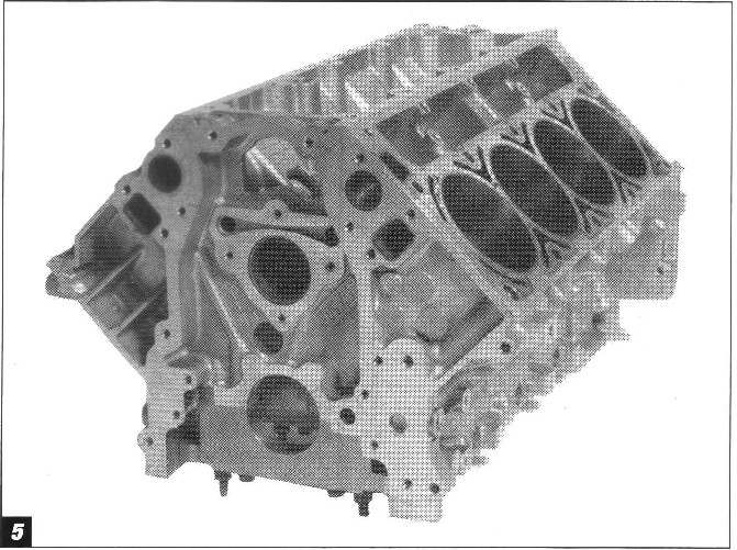
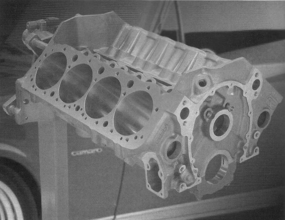
5 Metal Mania |
5 メタルマニア
何十年もの間、ほとんどのブロックは鋳鉄で作られてきた。しかし、最近の数年は製造者はアルミニウム合金ブロックを軽量化のために使い始めている。しかしアルミニウムは柔らかい金属であるため、ほとんどのアルミニウムブロックは鋳鉄のシリンダーライナーを耐久性向上のために組み合わせて利用している。耐久性を考えた時、長期にわたるトラブルのない働きのために、シリンダーライナーは特定の硬さ、低い摩擦係数、そして熱安定性を持たなければならない。 ほとんどのアルミシリンダーは鋳込みあるいは圧入したシリンダーライナーと組み合わされている。 |
|
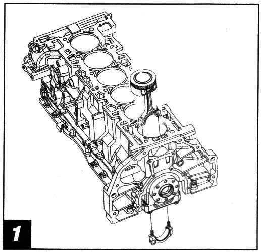
6 The Main Idea Main caps support an engine's rotating assembly (i.e. crankshaft, connecting rods, and pistons) and provide rigidity to the block. Most Chevy V-8s feature main caps retained with two-bolts, while high-performance blocks often use four bolts. Due to crankshaft length and design, an inline six-cylinder generally uses seven main caps while a V-8 uses five. To precisely position the crankshaft, all main-bearing caps are fitted with bearing inserts at each crankshaft journal. These inserts allow an oil film to form over the crankshaft journals, reducing friction. Critical to the main cap's design and operation is oil clearance and crankshaft end-play. If the main-cap bearing clearance is too small, excessive heat will be generated, thus causing bearing and crankshaft damage. If the clearance is too great, the crankshaft can hammer the bearing and cause engine failure. The rear main- cap bearing by design provides limited fore-and-aft movement (end-play) of the crankshaft.
|
6 メインアイデア(訳注:主たるアイデアとメインボルトのアイデアをかけている)
メインキャップはエンジンの回転部分(つまりクランクシャフト、コンロッド、そしてピストン)を支え、ブロックの安定性をもたらす。ハイパフォーマンスブロックがしばしば4つのボルトを使う一方、大部分のシェビーV8のメインキャップは2ボルトにとどまっている。クランクシャフトの長さとデザインへの制約から、直列6気筒では通常7つのメインキャップを使い、V-8は5つ使う。クランクシャフトの位置を正確に定めるため、全てのメインベアリングキャップは各々のクランク車夫とジャーナルにおいてベアリングインサートとフィットされなければならない。これらのインサートはクランクシャフトジャーナル上に油膜を作らせ、摩擦を軽減する。メインキャップのデザインと作業にとって重要なことはオイルクリアランスとクランクシャフトエンド遊びである。もしメインキャップベアリングの間隔が小さすぎると、余計な熱が発生され、結果としてベアリングとクランクシャフトを傷める。間隔が大きすぎると、クランクシャフトはベアリングを打撃しエンジンを壊してしまう。リアメインキャップベアリングはデザインによってクランクシャフトに制約された前後動(エンド遊び)を与えるようになっている。 |
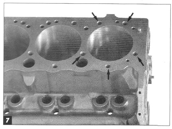
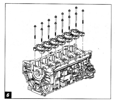
7 Head bolts per cylinder Cylinder-head sealing is critical in block configuration. To provide even clamping and minimize the chance of warpage, engineers designed the original small- block Chevy with five cylinder-head bolts surrounding each cylinder to seal the combustion area. Each small-block head uses a total of 17 head bolts. The Gen III LS1 engine now employs only four bolts per cylinder for a total of 10 head bolts. |
7シリンダーあたりのヘッドボルト
シリンダーへットシーリングはブロックの設定にとって非常に重要である。均一な抑え力を与え、反りや歪みの危険性を最小にするために、エンジニアはオリジナルスモールブロックシェビーを燃焼空間を密閉するシリンダーごとの周囲のボルトを5個にデザインした。スモールブロックのヘッドはそれぞれ計17のヘッドボルトを使っている。第三世代LS1エンジンはシリンダーあたり4つだけで、合計で10個のヘッドボルトを使っている。 |

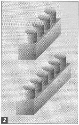
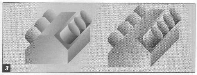
8 Give 'Em Space |
8 間隔を与えよ
ボア間隔はエンジンの長さに最も影響する。上に示したのはビックブロック(左)とスモールブロック(右) ボックブロックのボアサイズはスモールブロックより大きいことに注目。ボアサイズ、コンロッド幅、メインベアリング幅は全てエンジンの全体サイズに影響する。より広いボア間隔は明白に、より大きいボアと大きい排気量を可能にする。それから、左側のシリンダーバンクが右側よりもずっと前にあることにも注目。これによってそれぞれのコンロッドジャーナルはそれぞれのシリンダーボアの中心に位置することができる。 |
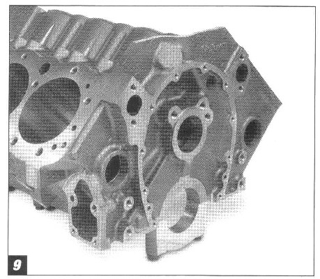
9 Fluid Dynamics
|
9 液体力学
全ての主要な部品を厳密に正しく設置することに加え、ブロックは潤滑と冷却双方の液体についても重要である。スモールブロックV8をオイルと水の両方の道についての例として用いる。 潤滑系では、オイルはパンの中でスタートし、オイルポンプで加圧され、メインキャップを押し通されオイルフィルターへと出て行く。オイルはフィルターの外側を流れ降り、フィルター媒体を通って内側へと流れる、そこではそれからカムジャーナルの上、ブロック中央にあるメインオイルギャラリーへとベルハウジング空間の中のアングルパッセージを押し上げられる。もし剥き出しのブロックをカムベアリング無しで見たら、5個のカムジャーナルそれぞれの周りにオイルをメインへと導く道筋を見ることができるだろう。オイルはそれからカムジャーナルの周りを押し下げられブロックのメインジャーナルへと向かう。メインの巣の中の穴はオイルをクランクシャフトへ、そしてそれからロッドジャーナルへと供給する。ここでロッドを通って漏れた分はクランクによって飛ばされ飛沫がカムローブを潤滑する。(あなたはローブは圧力供給だと思っていたんじゃないですか?) リフターバレーの中のメインオイル流路はまたリフターの中を通る2つの並行したオイルギャレーへも供給する。これらの流路はリフターにオイルを共有し、さらにプッシュロッドを通ってロッカーアーム、バルブスプリング、そしてバルブトレインの残りを潤滑する。ここからは、オイルはヘッドとブロックの中の道を通ってオイルパンへと落ちていく、そしてオイルパンではまた全ての繰り返しが始まる。 冷却系では、シェビーエンジンはクーラントをラジエーターからロアーラジエーターホースを通して吸い上げポンプで圧力化する。それからその液体はブロックに入り、そしてシリンダーを通過してブロックの中に鋳込まれたウォータージャケットを通ってブロックの両サイドを流れ落ちる。クーラントはブロックの中を前から後ろへと流れ、それからシリンダーヘッドへ後部で入り前方へと流れる。クーラント流路はまた、シリンダーヘッドへも鋳込まれてあり、水を特に燃焼室の周りと排気バルブへと導き、デトネーションを避ける助けとなる。 クーラントがシリンダーヘッドの全部へと到達したら、水はインテークマニホールドへサーモスタット直下から入る。サーモスタットの仕事は水温が最低温度に到達するまで流れを制限することである。弁はそれから開き、クーラントはそれからウォーターポンプの水圧によってラジエーターへと戻される、そしてそこでまた全てが繰り返され始める。 LT1とLT4の第二世代スモールブロックではリバースクーリングシステム、より発展したシリンダーヘッド冷却のためクーラントが最初にシリンダーヘッドへと直接流れそれからブロックへと流れるシステムに設計された。しかし、LS1第三世代エンジンが設計された時には、元の流れに戻された。(訳注:リバースフローではヘッド冷却が著しく向上する反面、他の部分の冷却能はかなり落ちる。ヘッドで吸収した熱を他の部分で放熱してからラジエーターに達するので、あまり賢い方法ではない。) |